
izdelki kategorija
- FM oddajnik
- 0-50w 50w-1000w 2kw-10kw 10kw +
- TV oddajnik
- 0-50w 50-1kw 2kw-10kw
- FM antene
- TV Antenna
- Antenna pripomočki
- Cable priključek moč Splitter Dummy Load
- RF Transistor
- Napajanje
- avdio oprema
- DTV Front End oprema
- Link sistem
- STL sistem Sistem Mikrovalovna Link
- FM radio
- power Meter
- Ostali izdelki
- Posebno za koronavirus
izdelki Oznake
Fmuser strani
- es.fmuser.net
- it.fmuser.net
- fr.fmuser.net
- de.fmuser.net
- af.fmuser.net -> afrikanščina
- sq.fmuser.net -> albanski
- ar.fmuser.net -> arabščina
- hy.fmuser.net -> Armenščina
- az.fmuser.net -> azerbajdžanski
- eu.fmuser.net -> baskovščina
- be.fmuser.net -> belorusko
- bg.fmuser.net -> bolgarščina
- ca.fmuser.net -> katalonščina
- zh-CN.fmuser.net -> kitajščina (poenostavljena)
- zh-TW.fmuser.net -> kitajščina (tradicionalno)
- hr.fmuser.net -> hrvaški
- cs.fmuser.net -> češčina
- da.fmuser.net -> danski
- nl.fmuser.net -> nizozemščina
- et.fmuser.net -> estonščina
- tl.fmuser.net -> filipinsko
- fi.fmuser.net -> finski
- fr.fmuser.net -> francosko
- gl.fmuser.net -> galicijščina
- ka.fmuser.net -> gruzijski
- de.fmuser.net -> nemščina
- el.fmuser.net -> grščina
- ht.fmuser.net -> haitijska kreolščina
- iw.fmuser.net -> hebrejščina
- hi.fmuser.net -> hindujščina
- hu.fmuser.net -> madžarščina
- is.fmuser.net -> islandski
- id.fmuser.net -> indonezijski
- ga.fmuser.net -> irski
- it.fmuser.net -> italijanščina
- ja.fmuser.net -> japonski
- ko.fmuser.net -> korejski
- lv.fmuser.net -> latvijski
- lt.fmuser.net -> litovščina
- mk.fmuser.net -> makedonščina
- ms.fmuser.net -> malajščina
- mt.fmuser.net -> malteščina
- no.fmuser.net -> norveščina
- fa.fmuser.net -> perzijski
- pl.fmuser.net -> poljščina
- pt.fmuser.net -> portugalščina
- ro.fmuser.net -> romunščina
- ru.fmuser.net -> ruščina
- sr.fmuser.net -> srbščina
- sk.fmuser.net -> slovaški
- sl.fmuser.net -> slovenščina
- es.fmuser.net -> španščina
- sw.fmuser.net -> svahili
- sv.fmuser.net -> švedščina
- th.fmuser.net -> tajska
- tr.fmuser.net -> turški
- uk.fmuser.net -> ukrajinski
- ur.fmuser.net -> urdujščina
- vi.fmuser.net -> Vietnamščina
- cy.fmuser.net -> valižanščina
- yi.fmuser.net -> jidiš
Preprost in ugoden DIY - kako narediti FM oddajnik?
Ali neradi kupujete radijske oddajnike zaradi visoke cene in niste seznanjeni z načelom dela? Zakaj ne bi najprej naredili preprostega in praktičnega FM radijskega oddajnika ali FM oddajnika? Ta vadnica vam bo podrobno predstavila, kako narediti in sestaviti delujoč oddajnik FM, ne glede na to, ali ste amater ali veteran, z le nekaj minutami branja in majhnimi stroški materiala. Naučili se boste, kako narediti in sestaviti preprost in praktični oddajnik za radijsko oddajanje FM. Poleg tega ta vadnica ne samo izboljša vaše praktične sposobnosti, temveč tudi prihrani drage stroške nakupa in vzdrževanja. Pripravite se na to!
Vsakdo lahko kupi FM anteno in zažene svojo radijsko postajo. Vse, kar potrebujete, je ustrezna oprema in seveda licenca FCC, ki je ni tako težko dobiti. Če ste že kdaj sanjali o lastni radijski postaji, je tako enostavno kot najti distributerja opreme za radijsko oddajanje, ki je specializiran za prodajo anten za radijsko oddajanje. FMUSER lahko uresniči vaše sanje. Specializirani smo za opremo za radijsko oddajanje in po potrebi kupcem pomagamo pridobiti licenco FCC. Lahko vam celo pomagamo zgraditi svojo radijsko postajo. Imamo najnižje cene za vso opremo, ki jo potrebujete za svojo radijsko oddajo. Kontakt FMUSER še danes!
Delitev je skrb!
Če iščete, kako narediti anteno FM oddajnika na dolge razdalje, prosimo, obiščite to vadnico:
Kako narediti svojo FM radijsko anteno | Osnove in vaje o domačih FM antenah
1. Stvari, ki jih morate vedeti, preden začnete
2. Ustvarjanje preprostega radijskega oddajnika
3. Kako narediti FM oddajnik z dolgim dosegom 5 km?
4. Kako narediti FM oddajnik z nizko močjo?
5. Kako narediti zelo preprost FM oddajnik?
6. Kako narediti preprost IPOD FM oddajnik?
Najboljši proračunski prenosnik radia z nizko porabo v letu 2021
1. Stvari, ki jih morate vedeti, preden začnete
Preberite tudi: Kakšna je razlika med AM in FM?
|
Ime |
Vzorec grafa |
funkcije |
|
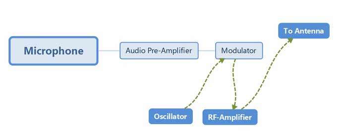
Napajanje |
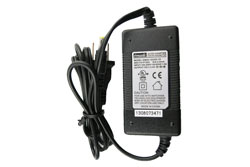 |
Zagotavljanje električnega signala za upravljanje oddajnika. |
|
Oscilator |
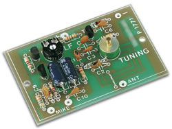 |
Ustvarjanje izmeničnega toka, nosilnega vala, ki ga oddajnik pošilja skozi anteno. |
|
Modulator |
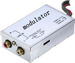 |
Dodajanje informacij nosilnemu valu. V primeru FM (frekvenčna modulacija) modulator bodisi nekoliko poveča ali zmanjša frekvenco nosilnega vala. |
|
Ojačevalnik |
 |
Povečanje moči vala. Močnejši ojačevalniki omogočajo večje območje oddajanja. |
|
Antena |
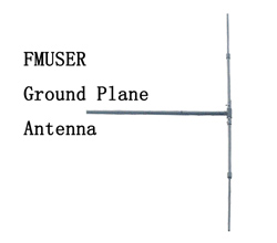 |
Pretvorba ojačenega signala v radijske valove. |
Ljudje pogosto imenujejo antene iz zraka. Za radijske postaje FM se antene običajno nanašajo na antene za radijsko oddajanje FM. Obstajata dve vrsti takih anten. Nameščeni so na oddajnem koncu (kar ustreza oddajniku FM radijskega oddajanja) in sprejemnem koncu (radijski sprejemnik FM) Čeprav so nameščeni na različnih geografskih lokacijah, so si glede na načela dela podobni.
Preberite tudi: Kako narediti svojo FM radijsko anteno | Osnove in vaje o domačih FM antenah
Tako antena na oddajnem koncu kot antena na sprejemnem koncu delujeta na radijske valove. Glavna naloga antene na oddajnem koncu je sprejemati in oddajati električne signale, ki jih ustvarja oddajnik FM radijskega oddajanja, in jih oddajati, medtem ko je sprejemna končna antena odgovorna za sprejem teh radijskih valov. val. Omeniti velja, da ti radijski valovi lahko prevozijo precejšnjo razdaljo (lahko jih celo prenašajo v vesolje). Če želite torej sprejeti te radijske valove, ki se prenašajo na dolge razdalje, mora biti sprejemnik zelo zmogljiv, sicer je enostavno Vzrok za različne težave, kot so težave z motnjami hrupa.
Če želite ustvariti preprost radijski oddajnik, morate v žici ustvariti hitro spreminjajoč se električni tok. To lahko storite s hitrim priklopom in odklopom baterije, kot je ta:
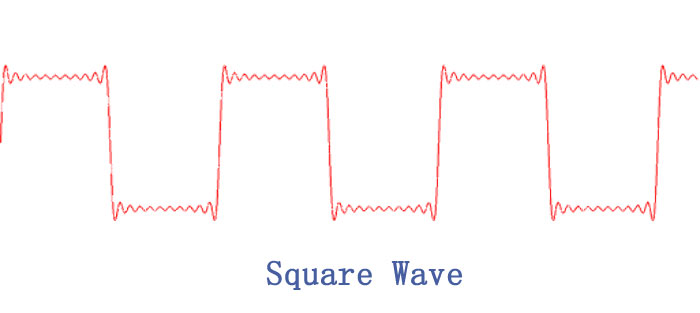
Ko priključite baterijo, je napetost v žici 1.5 volta in ko jo odklopite, je napetost nič voltov.
S hitrim priklopom in odklopom baterije ustvarite kvadratni val, ki niha med 0 in 1.5 volta.
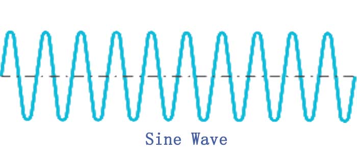
* Sinusni val gladko niha med, na primer, 10 volti in -10 volti.
Preberite tudi: Najboljših 9 najboljših oddajnikov radijskih oddajnikov, dobaviteljev in proizvajalcev s Kitajske / ZDA / Evrope v letu 2021
Prenos informacij
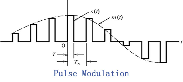
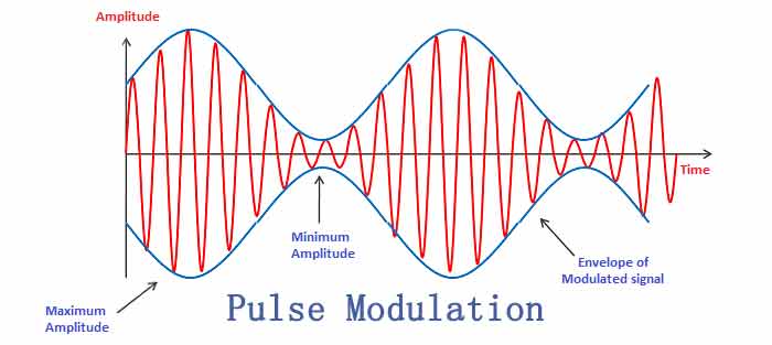
Če imate sinusni val in oddajnik, ki sinusni val oddaja v vesolje z anteno, imate radijsko postajo. Edina težava je, da sinusni val ne vsebuje nobenih informacij. Val morate na nek način modulirati, da na njem kodirate informacije. Obstajajo trije običajni načini moduliranja sinusnega vala:
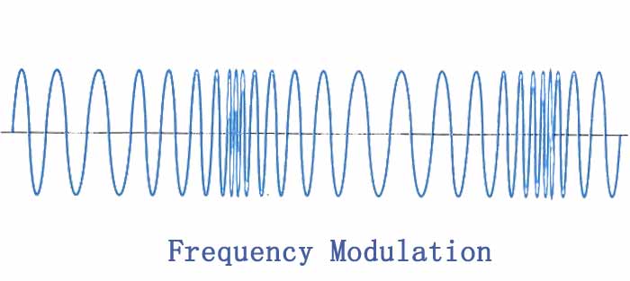
Frekvenčna modulacija - FM radijske postaje in stotine drugih brezžičnih tehnologij (vključno z zvočnim delom televizijskega signala, brezžičnimi telefoni, mobilnimi telefoni itd.) Uporabljajo frekvenčno modulacijo. Prednost FM je, da je v veliki meri odporen na statiko. V FM se frekvenca sinusnega vala oddajnika zelo malo spreminja glede na informacijski signal.
3. Kako narediti FM oddajnik z dolgim dosegom 5 km?
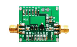
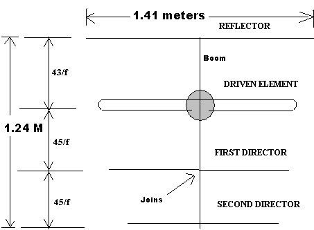
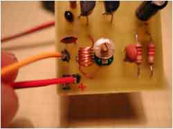
Tukaj predstavljamo FM oddajnik dolgega dosega, ki lahko pokriva razumno razdaljo 5 kilometrov / 3 milj in več z enojno vatno RF močjo s podrobnostmi polnega kroga, materialom in postopkom testiranja. Z 12 voltom DC bo dobil 1 watt RF moč. Z Yagi anteno, ki je videti kot zgodnje dni TV antene z aluminijastimi cevmi na obeh oddajnikih in sprejemnikih, ki gledata drug na drugega na liniji pogleda, je lahko območje do 5 km / 3 milj.
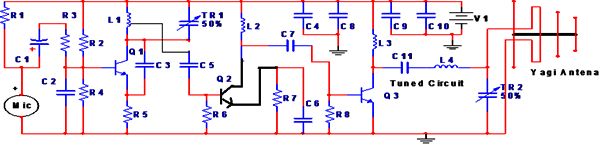
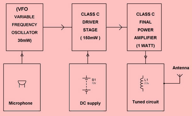
Ta FM oddajnik ima stopnje 3 RF.
A (VFO) Oscilator spremenljive frekvence (30 mw),
Q3 mora biti 2N3866 s hladilnikom za ustrezno območje. Vendar pa je mogoče uporabiti 2N 2219, ki bo drastično ogrozil razpon
Preberite tudi: Kaj je nizkoprepustni filter in kako zgraditi nizkoprepustni filter?
Testiranje:
Najprej uporabite preprosto enojno žico 75CM, ki stoji ravno kot antena, da dobite vrsto merilnikov 100-200 v zaprtih prostorih. Teleskopska antena podobne dolžine je prav tako primerna za testiranje, kar bo dalo le približno merilno območje 100-200. Ampak nikoli ne gredo dlje kot 79 CM antene žice misli, da bo pokrival višji razpon. V bistvu, če boste to storili, bo obseg padel.
Frekvenco oddajnika lahko nastavite s frekvenčnim pasom 88 na 108 MHz, tako da prilagodite TR1 (Trimmer 1) VFO ali spremenite razmik med tuljavo L1.
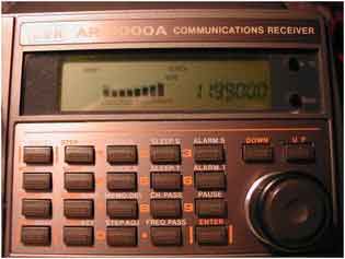
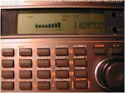
OPOMBA: Ne poskušajte preizkusiti enote zvečer do zvečer, ker bodo takrat aktivne številne zmogljive FM postaje. Preizkusite ga samo podnevi. Nekaj ljudi je imelo težave s tem vezjem, če ni pravilno spajkano. Največja težava je, da ne vemo, ali sploh niha, saj je frekvenca izven obsega najbolj preprostih osciloskopov. Morda boste potrebovali uporabo radiofrekvenčnega števca, ki je zelo drag. Torej, če želite vedeti, da niha, in samo ugotoviti, na kateri frekvenci, je najpreprostejši način, da mobilni telefon z FM radiem (ali katerim koli FM radiem) postavite v način iskanja blizu vašega oddajnika, da slišite nekaj zvoka, medtem ko tapnete mikrofon. Prosimo, upoštevajte, da bo zelo blizu oddajnika več frekvenc, ki se odzivajo na mikrofon, in ena se bo zmedla. Pojdite, vsaj 30 metrov stran od oddajnika po začetnem preizkusu, kot je preverjeno zgoraj. Tam zaslon daje samo eno frekvenco, na katero dobi najboljši jasen zvok, in vse druge frekvence, ki oddajajo sikajoč zvok, to je frekvenca, ki jo deluje oddajnik. Trimer TR1a prilagodite zelo zelo zelo (približno 1 stopinjo) malo v smeri urnega kazalca ali v nasprotni smeri urnega kazalca, frekvenca prenosa se bo spremenila. Nato dajte mobilni telefon na ponovno iskanje in iskanje frekvence. Če je zelo blizu močnega oddajnika, dosega ne boste dobili. Ponovno spremenite frekvenco, da se premaknete na 106 MHz, kjer običajno ni komercialnega prenosa.
Območje prenosa se prilagodi s TR2. Za to uporabite več merilnikov v enosmernem načinu 250 mA v seriji z napajanjem 12 in nastavite trimer TR2, medtem ko je tok največji. Prilagodite tok okoli 75 mA (pri 12 Volt DC, ki ga napaja dober adapter) ali maksimalni tok s trimerjem 2 in povejte o 85 mA. Od vrha, medtem ko obračate v smeri urinega kazalca, bo tok padel ali pa, ko se obračate proti smeri urinega kazalca, bo tudi padel. In to je najboljši položaj TR2-a za popolno napajanje antene. Prosimo, upoštevajte Q3, okroglo kovinsko ohišje mora biti popolnoma pokrito s črnim hladilnikom, brez katerega se bo slabo segrevalo in končno sežgalo. V okrog 100mA na 12 volt mora pokrivati dober razpon in biti topel, vendar onkraj tega trenutnega, čeprav lahko pokriva daljše območje, se mora zelo slabo segreti in verjetno ne bo uspel. ogrejte samo kot toplo. Če se segreje slabo se izklopi in zmanjša tok.
Pomembno opozorilo:
Izhod se napaja na koaksialni kabel (ki se običajno uporablja za kabelsko televizijo), ki je skoraj usklajen z anteno Yagi (čeprav je 300 ohm) impedanca 75 ohmov s trimerjem TR 2 nastavljenega vezja za največjo moč dobave tovora, tj. / GP antena. Oddajnika ne smete nikoli napajati brez antene (tj. Obremenitve), v tem primeru skupna moč ustvari razmerje stoječih valov SWR na močnostnem tranzistorju Q3, ki ga močno segreje, da povzroči okvaro.
Preberite tudi: Kaj je VSWR in kako izmeriti VSWR?
Opombe
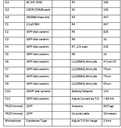
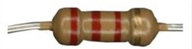
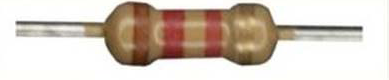
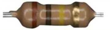
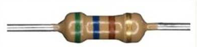
1. Priporočljivo je, da za spajkanje vključite katerega koli elektronika, če nimate predhodnih strokovnih izkušenj s spajkanjem in identifikacijo komponent. Prekomerno ogrevanje, ki traja več kot 2 sekund, lahko poškoduje komponento. Uporabljajte samo spajkalnik 25 watt. Najpomembnejše je dajanje prave vrednosti upora. Previdno preberite barve, da ugotovite njeno vrednost. Če je na voljo multimeter, ga bolje izmerite v ohmih / Kohms območju. Ne sme dati točne vrednosti. Plus ali minus 10% je sprejemljivo. Za branje diskovnih keramičnih kondenzatorjev je potrebno strokovno znanje. Postavite jih pravilno. Oglejte si sliko.
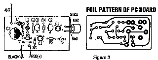
Tukaj je shema, PC vzorec krovu, in postavitev delov za nizko powered FM oddajnik. Razpon oddajnika, ko teče na 9V je približno 300 metrov. To poteka od 12V povečuje obseg približno 400 noge. Ta oddajnik se ne sme uporabljati kot sobe ali telefonsko bug.
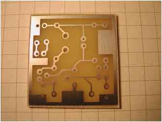
|
 |
||
|
shematski |
PC Board Postavitev in deli umestitev |
||
|
Del |
Skupna količina |
Opis |
Zamenjave |
|
C1 |
1 |
0.001uf Disc Capacitor |
|
|
C2 |
1 |
5.6pf Disc Capacitor |
|
|
C3, C4 |
2 |
10uf elektrolitski kondenzator |
|
|
C5 |
1 |
C5 1 3-18pf Nastavljiv pokrov |
|
|
R1 |
1 |
270 1 Ohm / 8W upor |
270 1 Ohm / 4W upor |
| R2, R5, R6 |
3 |
4.7k 1 / 8W upor |
4.7K 1 / 4W upor |
|
R3 |
1 |
10k 1 / 8W upor |
10K 1 / 4W upor |
|
R4 |
1 |
100k 1 / 8W upor |
100K 1 / 4W upor |
|
Q1, Q2 |
2 |
2N2222A NPN Transistor |
2N3904, NTE123A |
|
L1, L2 |
2 |
5 Turn Air temeljnega Coil |
|
|
MIC |
1 |
Electret mikrofon |
|
|
MISC |
1 |
9V baterije Snap, PC Board, žice za anteno |
|
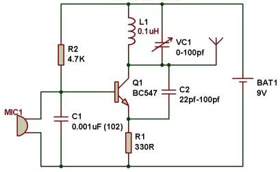
5. Kako narediti zelo preprost FM oddajnik?
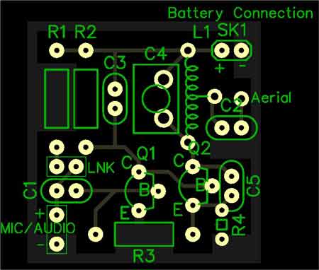
Ta vzorčni test vam pokaže, kako sestaviti zelo preprost FM oddajnik iz trinajstih komponent, tiskanega vezja (PCB) in 9v baterije. Ta projekt je bil zasnovan za namestitev na tiskano vezje, vendar vam ni treba. Projekt lahko sestavite na plošči Vero (tračna plošča) ali katerem koli drugem 0.1-palčnem slogu projektne plošče. Če želite samo eksperimentirati s tem vezjem, niti plošče ne potrebujete; komponente lahko preprosto spajkate in pustite, da se zaključeni projekt nasloni na delovno ploščo. Ne glede na to, kateri slog izberete, poskušajte, da so vsi kabli komponent lepi in kratki. Lahko bi tudi PCB naredili veliko manjši od tistega, ki je prikazan tukaj in je približno 3 cm kvadrat. To je dobra velikost, da je enota majhna, vendar je za začetnike prijetnejša. Če bi radi naredili enega res majhnega, bi lahko uporabili vse dele SMT.
Preberite tudi: Kako odpraviti hrup na AM in FM sprejemniku?
Vrednost kondenzatorja C5 nadzoruje frekvenčno območje prenosa.
Ti so le približni, saj frekvenco določa L1 in specifikacija tranzistorjev, vendar so bili ti obsegi opaženi v prototipni enoti. Upoštevajte tudi, da bližje kot so navitja tuljave, manjša bo frekvenca. Z rahlim stiskanjem tuljave je frekvenca prenosa padla za več kot 1 MHz.
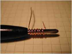
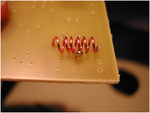
Prva misel je vetrna in namestitev tuljave. Tuljava je preprosto dolga 0.6 mm / 22swg bakrene žice, navite v tuljavo. Vzemite golo bakreno žico dolžine 10 cm in jo navite okoli primernega oblikovalca; rezilo draguljarskega izvijača ali igle za pletenje je idealno.
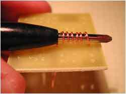
Ko je tuljava navita, jo zaenkrat pustite na navitju, da se med namestitvijo ne bo deformirala. Vsak konec tuljave potisnite v pravilno luknjo PCB, ki po potrebi raztegne tuljavo, tako da so njena navitja enakomerno razporejena. Obrnite tiskano vezje in spajkajte na obeh koncih tuljave.
Nato namestite preostale komponente, razen tranzistorjev, v poljubnem vrstnem redu, ki se vam zdi najbolj prijetno.
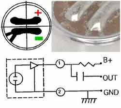
Ko pride čas za spajkanje na mikrofon, morate biti previdni. Na dnu mikrofona bosta dve spajkalni blazinici. Če natančno pogledate, mora biti ena od blazinic povezana s ohišjem; to je negativno.
Za ta oddajnik ne potrebujete ničesar pametnega v antenah. Dlje ko je antenska žica, daljši bo obseg prenosa, vendar za preskušanje samo povežite dolžino 25 cm.
V redu, zdaj za zapleteno bit. Če predpostavimo, da ste vse skupaj pravilno povezali, potem boste glede na uporabljene tranzistorje, toleranco komponent, značilnosti vaše tuljave in položaj kondenzatorja trimera, ko priključite baterijo, oddajali zvok nekje v FM pasu, verjetno med 80MHz in 150MHz.
Drobljena tuljava za znižanje frekvence
Zmanjšanje vrednosti R4 bo povečalo pogon na Q2 in s tem povečalo izhodno moč oddajnika. Če pa boste R4 preveč zmanjšali, boste skrajšali življenjsko dobo baterije in sčasoma lahko uničili tranzistor Q2.
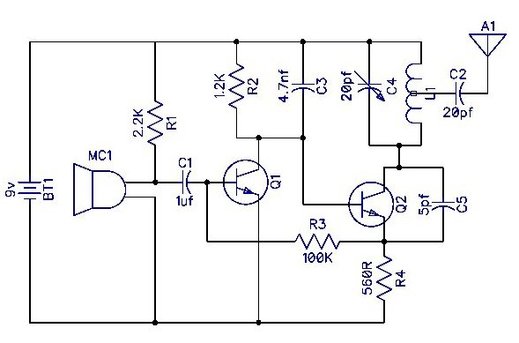
| Sestavni deli | Razkritje | Komentarji |
| R1 |
2.2 K 5% |
 |
| R2 | 1.2 K 5% |
 |
| R3 | 100 K 5% |
 |
| R4 | 560 ohmov 5% |
 |
| C1 | 1UF |
|
| C2 | 22PF |
|
| C3 | 4.7NF |
|
| C4 | 20PF Varcap |
 |
| C5 | 5.6PF | Glejte besedilo o izbiri primerne vrednosti |
| Q1 | Gen NPN | Ali skoraj kateri koli majhen NPN tranzistor |
| Q2 | General NPN | Ali skoraj kateri koli majhen NPN tranzistor |
| MC1 | Izvol. Mic |
 |
| L1 | Glej Besedilo |
|
| A1 | Glej Besedilo |
|
| BT1 | 9V sponka za baterijo |
|
Preberite tudi: Kaj je QAM: kvadraturna amplitudna modulacija
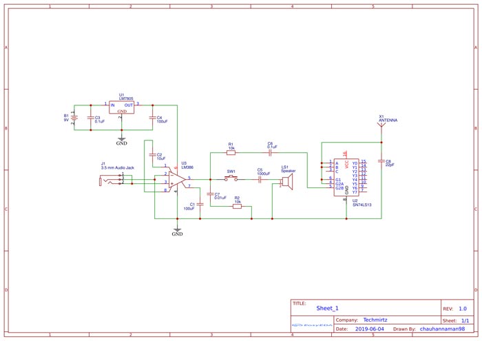
6. Kako narediti preprost oddajnik IPOD FM?
Stvari, uporabljene v tem projektu
1. TI SN74LS138N - Schmittov sprožilec s 4 vhodnimi NAND vrati
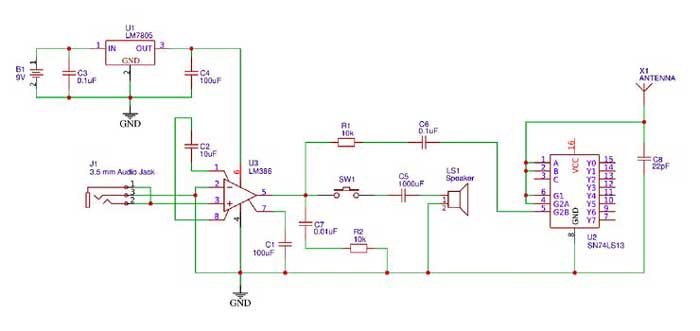
Zahvaljujoč pristopu Tonyja Van Roona je uglasitev tega vezja FM oddajnika zelo enostavna v primerjavi z drugimi vezji, saj nima Induktorja ali trimera. Za začetek preprosto vklopite vezje in zvočnik priključite na vezje, kot je prikazano v zgornjem vezju. Zdaj priključite iPod ali katero koli zvočno napravo na 3.5-milimetrski priključek in predvajajte glasbo. Zvok bi morali slišati prek zvočnika. V nasprotnem primeru je težava v povezavah LM386. Če je zvok slišen, odklopite zvočnik in nadaljujte s postopkom uglaševanja.
Uporabite radio s sprejemnikom in začnite obračati gumb, da veste, na kateri frekvenci oddaja oscilator. Najboljši način je preveriti približno 100 MHz, saj bi najverjetneje obšel to frekvenco. Naj bo vaša glasnost največja in počasi melodirajte, dokler ne slišite skladbe, ki se predvaja prek vašega zvočnega vira.
1. Če slišite nenavaden šum pri določeni frekvenci in želite ugotoviti, ali je to vaša frekvenca oscilatorja. Preprosto izklopite vezje in ga ponovno vklopite, če je frekvenca pravilna, bi moral vaš radio oddajati prasketanje
2. Anteno radia razširite na celotno dolžino in jo najprej namestite blizu vezja
3. Spremenite delovno napetost znotraj 4.5 do 5 V, da spremenite frekvenco, na kateri oddajate, ker se je včasih frekvenca morda ujemala z drugim priljubljenim FM pasom.
Delitev je skrb!
Če potrebujete več informacij o konzoli FM oddajne opreme, se obrnite na mene po elektronski pošti ali Whatsappu, cenimo vaše branje in vam želimo veliko sreče!

Pošljite nam | ZDAJ

Moj WhatsApp +8618319244009 Web | App
